
Self-Balancing Robot
I’ve always been fascinated by self-balancing robots that “stand up” on two wheels, so I decided to buy an off-the-shelf hardware kit (OSOYOO RC Two Wheel Robot) and see what I can make out of it. This robot had two DC motors that used to actuate the wheels that it used to keep itself upright on a surface. Out of the box, there were two problems: first, the motion of the robot was very slow and unresponsive, and second, the Bluetooth app to control it only worked on Android (I only have an iPhone). I decided to re-program the robot to make it able to move more responsively and sporty, and also modify it to hook it up to a RC controller so I can use a joystick to command the motion of the robot.
The self-balancing robot is an instance of an inverted pendulum system, which is a popular demonstration of using feedback control to stabilize an open-loop unstable system. It’s actually similar to the controls for stabilizing a quadcopter, which I had done (a mediocre job) previously, but this time I wanted to push the boundaries of the performance on a system that is slightly simpler and easier to test.
Model
Model of the system dynamics
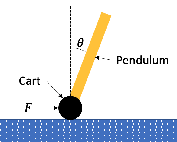
The dynamics of the system is typically modeled as a “inverted pendulum on cart”. This system assumes that there are two point masses - A pendulum with a mass on the very end that is being supported at the base by a cart with a certain amount of mass. While this model is helpful for a robot that obviously has the majority of its mass attached to the tip of a pendulum, my robot has significant amount of mass distributed along the length of its short pendulum.
Therefore instead of modeling the pendulum as a point mass, I decided to model it with a given mass, as well a rotational inertia to capture the mass distribution. The mass of the cart in this case is the mass that does not tilt with the pendulum, such as the wheels and motors.
Controls
The robot is kept upright by actuating the motors that drive the tires. The overview of the control loop is that there are two PID controllers are used in the form of cascade control, in which the output of one controller becomes the setpoint for another. In this case, there is one PID controller that controls the pitch angle (θ) of the robot, and another PID controller that controls the velocity (V) of the robot. This works very well because they are both controlling variables that can be approximated as linear, first or second order systems, which PID controllers are suitable for. While the pitch controller outputs motor torque to control pitch, the velocity controller outputs the pitch setpoint in order to control velocity. It also helps separate the reverse-acting nature of pitch control (increasing torque decreases pitch) and direct-acting nature of velocity control (increasing pitch increases velocity). See block diagram below for more details.
In addition to the velocity and pitch PID controllers, there is another PID controller that controls yaw rate of the robot. This enables the robot to rotate in place or gradually turn while moving forward. The output from this controller is fed as a differential to the right/left motors to turn the robot.
Control Block Diagram (Click to Enlarge)

Symbol Definitions (Click to Enlarge)
Simulation
In order to understand the dynamics and evaluate the performance of the controls a little better, I wrote a simulation script of the physics of the robot, as well as the control system using Python. The simulation contained the the dynamics of the system, as well as the feedback controllers described previously. Based on a set of initial conditions (x, V, θ, dθ/dt) the script simulated the motion of the robot and plotted results, as well as animated what the physical system looked like.
The second-order, coupled differential equations of motion of the system were derived using Newton’s laws of motion. The script calculated solutions using euler integration for simplicity and ease of use for prototyping. Constants used were ballpark guesses, which was sufficient for proof-of-concept.

Equations of Motion
One of the major lessons learned from the simulation was how to deal with the coupling between pitch control and velocity control. For instance - If the robot wants to accelerate forward, it must first move its base backwards to increase pitch (tilt forward). However, moving backwards decreases the velocity and increases the velocity error even more, causing the robot to increase pitch even more and overshoot the target velocity. This kind of behavior leads to unstable oscillations and can lead to the robot losing balance and falling.
This pitch-velocity coupling issue was solved using two methods: low-pass-filter (LPF) and center of velocity. Because the pitch control happens at higher speeds than velocity control, I decoupled the two using a LPF. The velocity feedback into the velocity controller is passed through a LPF with a time constant ≈ 0.2s to eliminate the high frequency velocity oscillations caused by the pitch control. Because the LPF causes a lag in the velocity feedback, this leads to a less-responsive system, though that is still much better than an unstable system without the LPF.
See results of simulation below with/without the LPF. The simulation is started with the robot having some initial velocity, and it is being commanded to come to a complete stop. With the LPF, the robot comes to a stop relatively quickly and smoothly. However, without the LPF, the robot repeatedly overshoots the target velocity and its motion becomes unstable.
With Velocity LPF - Stable

Without Velocity LPF - Unstable

See force being clipped at 50N - this is a constraint to roughly model the maximum motor torque in the real system

Center of velocity moves little when pendulum oscillates
Another method used to reduce the pitch-velocity coupling was to use the velocity of some other location on the robot, rather than just the wheels. When the robot sways back-and-forth in-place, there is a point that stays relatively stationary, even though the wheels may be in motion. I called this point the center of velocity of the robot, and it moves smoothly with the robot despite oscillations in pitch. The exact height can probably be calculated using a combination of pendulum mass, rotational inertia, and CG, but I guessed this value watching the simulation. Although this does not completely eliminate the coupling, it helps to reduce the time constant used for the LPF and makes the system more responsive.

DC Motor
The DC motors are powered using voltage supplied by the motor driver and create a certain amount of torque. However, the amount of torque is not proportional to the voltage. For the pitch PID controller to work well, we want to control the amount of torque generated by the motor (not speed) to keep the system linear and second-order ( τ=Iα). Instead of voltage, electrical current is a better indicator of the motor torque, though it is more difficult to monitor/control. Instead, I decided to indirectly control the motor torque using the motor speed data from the encoders on the motor and regulating voltage. Using the mechanics of how DC motors work, we can use the following relation to calculate the voltage necessary to achieve a certain amount of torque. Constants were found from the motor datasheet.

Result
After some time tuning PID gains and LPF cutoff frequencies, the robot is able to move pretty agiley by commanding using a joystick on the RC controller. The bluetooth module sends data from the robot wirelessly to a computer so that the data can be reviewed to improve performance. I wrote a script to receive the data and plot it. Two plots below show two different running cases.
Plot showing data from robot when robot is oscillated fwd/backwards direction. Note the small error between the pitch (labeled th) measured and setpoint.
Plot showing data from robot when robot is accelerated from stand-still. Small oscillations in pitch at speed are most likely due to the slop in the geared motor.